product details
1、 Purpose: < br / >
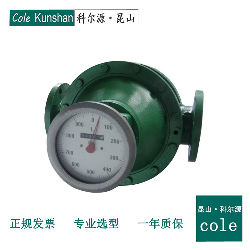
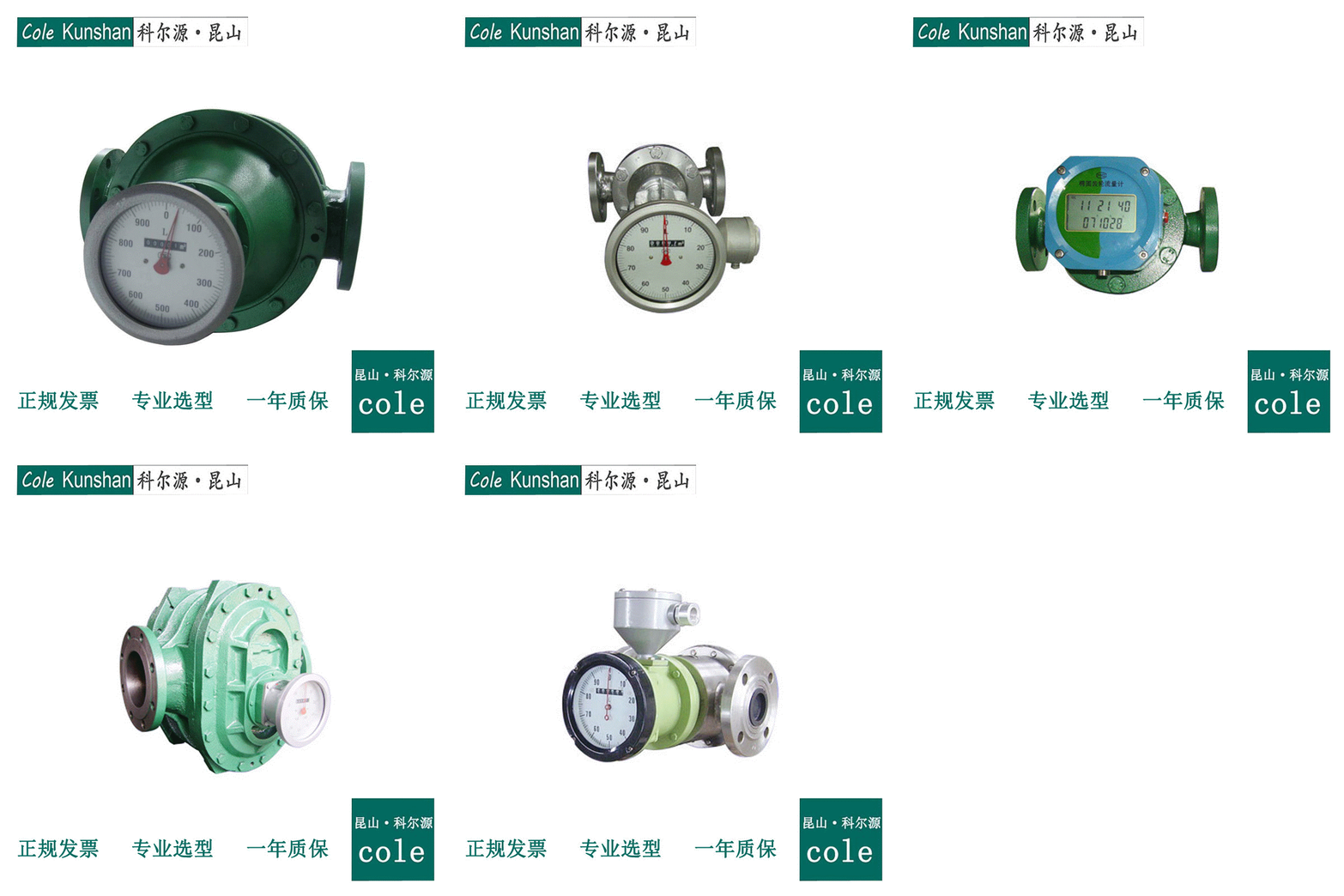
Elliptical gear flowmeter is a kind of light volumetric flow meter with pointer display, word wheel cumulative counting device and zero return device. It is widely used in liquid flow control in various industrial fields, and is suitable for various types of liquid measurement, such as crude oil, diesel oil, gasoline, etc. it has the characteristics of large range, high precision, convenient use and maintenance, etc. different manufacturing materials are selected, It can meet the liquid flow measurement in petroleum, chemical industry, medicine, food, metallurgy, electric power, transportation and other fields.
2、 Working principle and structure: < br / >
& nbsp;& nbsp; The flowmeter is composed of a metering box and a pair of elliptical gears installed in the metering box, and the upper and lower cover plates form a sealed moonshaped cavity (because of the rotation of the gears, it is not absolutely sealed) as the calculation unit of primary displacement. When the measured liquid enters the flow meter through the pipeline, a pair of gears are driven to rotate continuously due to the pressure difference at the inlet and outlet, and the liquid measured by the first moon shaped cavity is continuously transported to the outlet. The product of the number of revolutions of the elliptical gear and four times of each displacement is the total flow of the measured liquid (see Fig. 1 for the principle)< br />
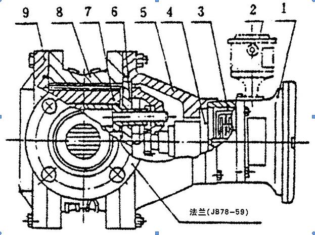
& nbsp; The flowmeter is mainly composed of shell, counter, elliptical gear and coupling (including magnetic coupling and axial coupling) (see Figure 2 for structure).
Figure 1 & nbsp; Schematic diagram of elliptical gear operation
Figure 2 & nbsp; Structure diagram of elliptical gear flowmeter
1. Counter & nbsp& nbsp;& nbsp;& nbsp; & nbsp;& nbsp;& nbsp; 2 transmitter & nbsp& nbsp;& nbsp; & nbsp;& nbsp; 3. Precision regulator (for use above DN50) < br / >
4. Sealed coupling & nbsp& nbsp;& nbsp;& nbsp;& nbsp; 5. Front cover & nbsp& nbsp;& nbsp;& nbsp;& nbsp;& nbsp;& nbsp; 6. Cover plate & nbsp& nbsp;& nbsp;& nbsp;& nbsp;& nbsp;& nbsp; 7. Elliptical gear < br / >
8. Shell & nbsp& nbsp;& nbsp; & nbsp; 9. Back cover
3、 Technical data: < br / >
(1) Ordinary cast iron type (a), cast steel type (E), stainless steel type (b) elliptical gear flowmeter
(2) High temperature cast iron type (TA), cast steel type (TE), stainless steel type (TB) elliptical gear flowmeter
(3) High viscosity cast iron type (NA) and cast steel type (NE) elliptical gear flowmeter
4、 Lc-13 oval gear flow transmitter
Lc-13 elliptical gear flow transmitter is composed of body and qf13 transmitter, which can convert liquid flow from tube to tube into electric pulse signal output. It can be used with El series display instruments produced by our factory (it can be used with other instruments that can accept the signal, such as microcomputer and display instruments). The total amount and instantaneous flow of liquid flowing through the pipeline can be directly displayed by electronic instrument, which is suitable for remote display, automatic control, computer refueling and other occasions< br />
1. Technical performance < br / >
1) Allowable basic error: & plusmn; 0.2%
2) Viscosity of the tested liquid: 0.6 ~ 200MPa. S < br / >
3) The measured liquid temperature: - 10 ~ + 65 ℃ < br / >
4) Maximum working pressure < br / >
Cast iron, stainless steel 1.6Mpa < br / >
Cast steel: dn20-25, 2.5MPa, dn-15, Dn40,6.4Mpa
5) Main materials: cast iron, cast steel, stainless steel < br / >
6) Pipe connecting flange: jb78-59, jb79-59 < br / >
7) Transmitter: qf13 < br / > transmitter
a. Power supply: 12VDC (already equipped in our plant's display instrument) < br / >
b. Pulse amplitude v = 4V (square wave) low level < 4.5V, < br / >
High level > 8.5V < br / >
c. Transmission distance: 1km (wire resistance of metal shielded wire & le; 39Ω)< br />
8) Electrical performance accuracy: & plusmn; 1 pulse < br / >
9) Explosion proof grade: IA Ⅱ CT5 < br / >
10) Explosion proof safety barrier model: nf713
5、 QF transmitter < br / >
& nbsp; The transmitter is installed on the oval gear flowmeter (or transmitter) with A1, E1 + T counter produced by our factory, which can transmit signals remotely. It can convert the flow of the measured medium into electric pulse signal, so as to realize the automatic control of the system< br />
& nbsp; QF transmitter is composed of high-frequency oscillator, detector, detection and shaping circuit. When the slotted metal piece rotates on the coupling coil of the oscillation circuit and detector, i.e. interferes with the magnetic line of force, it obtains a series of amplitude modulation signals. After detection, it is sent to the shaping circuit as a square wave. Due to the change of voltage drop on the load resistance, the current changes accordingly, At the same time, the two terminals of the transmitter have high and low level inversion< br />
& nbsp; Technical parameters < br / >
1. Working voltage: 12VDC & nbsp& nbsp;& nbsp;& nbsp;& nbsp;& nbsp;& nbsp;& nbsp; 2. Working voltage range: 11-15vdc < br / >
3. Output signal: v = 4V (square wave), low level < 4.5V, high level > 8.5V < br / >
4. Remote transmission distance: 1km (wire resistance of metal shielded wire & le; 39Ω)< br />
5. Ambient temperature: - 10 ~ + 65 ℃ & nbsp& nbsp;& nbsp;& nbsp; 6. Explosion proof grade: A: IA Ⅱ CT5 B: D Ⅱ BT4 < br / > 1
(3) QF transmitter output line connection < br / >
1. QF - Ⅰ transmitter output line connection & nbsp& nbsp;& nbsp;& nbsp;& nbsp;& nbsp;& nbsp; 2. QF - Ⅱ transmitter output line connection < br / >
(4) Outline and installation dimension of safety barrier (JF type) < br / >
Note: JF type safety barrier is available in our factory, which must be explained when ordering
(5) Explosion proof performance < br / >
& nbsp;& nbsp;& nbsp; IQF anti explosion transmitter is a kind of pulse transmitter used with elliptic gear flowmeter in IA Ⅱ CT5 and D Ⅱ BT4 places. The explosion-proof forms are intrinsically safe type and flameproof type respectively. There are obvious explosion-proof signs on the shell. IQF transmitter is connected with safety barrier and used with display instrument< br />
& nbsp;& nbsp;& nbsp;& nbsp;& nbsp;& nbsp;& nbsp;& nbsp;& nbsp;& nbsp;& nbsp;& nbsp;& nbsp;& nbsp;& nbsp;& nbsp;& nbsp;& nbsp;& nbsp;& nbsp;& nbsp;& nbsp;& nbsp;& nbsp;& nbsp;& nbsp;& nbsp;& nbsp;& nbsp;& nbsp;& nbsp;& nbsp;& nbsp;< br />
Precautions: < br / >
& nbsp; 1. IQF intrinsically safe type anti exploder is installed on a counter below (including Dn40) of LC type Dn40, BQF flameproof type anti exploder is installed on e + T counter above Dn40 of LC type, and the supply voltage of transmitter shall not exceed the rated voltage of safety barrier< br />
& nbsp; 2. IQF transmitter is used in explosion-proof situation, but it must be equipped with safety barrier, and the distributed inductance and capacitance of connecting wire are not more than 1.5mH and 0.1uF< br />
& nbsp; 3. QF transmitter is used in places where explosion-proof is not required< br />
Transmitter and LC series elliptical gear flowmeter with the transmitter parameter table
Diameter mm & nbsp& nbsp;& nbsp;& nbsp;& nbsp;& nbsp;
A1 counter
L/P
P/S
ten
zero point zero one
eleven point one one
fifteen
zero point one
four point one six
twenty
zero point one
eight point three three
twenty-five
zero point one
sixteen point one six
forty
one
four point one seven
A40
& nbsp;& nbsp;& nbsp;& nbsp;& nbsp;& nbsp;
Diameter mm
E1+T
L/P
P/S
ten
zero point one
sixty-six point seven
fifteen
one
eleven point one one
twenty
one
sixteen point six seven
twenty-five
one
twenty-seven point seven eight
forty
one
fifty-two point seven eight
A40
one
ninety-four point four four
Our factory also produces ZF, ag19 and GF-1 transmitters. Please read the operation manual of other products. L: l in the table; P: Pulse number, s: seconds< br />
6、 Operation manual of ps-20ma instantaneous flow meter < br / >
( 1) Instrument principle and function < br / >
& nbsp; Ps-20ma instantaneous flow meter adopts single-chip microcomputer technology, through its internal photoelectric pulse transmitter (the photoelectric pulse transmitter reduces the mechanical rotation and converts it into electric pulse signal by photoelectric method). The flow signal of the flowmeter is converted into digital signal for collection and calculation, and the instantaneous value of flow per second in operation is calculated according to the set relevant parameters, which is converted into 4-20mA current signal and 0-10V voltage signal for output. In addition, the instrument has pulse synchronous signal output, which is used as the signal source of ps-400 constant value control flow meter and similar flow meters of our company. It can be used as other pulse measurement signal source and serial communication function, and can be connected to the upper computer< br />
( 2) Features and application of instruments < br / >
& nbsp; The instrument has the features of accurate measurement, 12V DC power supply, 4-20mA current output and serial communication. It is easy to operate and has high cost performance. It is suitable for centralized control and other occasions requiring signal acquisition< br />
& nbsp;( 3) Instrument performance index < br / >
& nbsp; 1. Power supply ?eighteen
twenty-five
three hundred
two hundred and two
two hundred and fifty-two
one hundred and eighty-five
one hundred and thirty-five
one hundred
four
eighteen
forty
three hundred
two hundred and two
two hundred and ninety-three
two hundred and eight
one hundred and sixty-five
one hundred and twenty-five
four
twenty-three
fifty
three hundred and eighty-four
two hundred and sixty-two
three hundred and ninety-four
three hundred and twelve
one hundred and seventy-five
one hundred and thirty-five
four
twenty-three
eighty
four hundred and fifty
three hundred and thirty-seven
four hundred and fifty-two
three hundred and thirty-two
two hundred and ten
one hundred and seventy
eight
twenty-three
one hundred
five hundred and fifty-five
four hundred and forty-two
four hundred and seventy-eight
three hundred and ten
two hundred and fifty
two hundred
eight
twenty-five
one hundred and fifty
five hundred and forty
five hundred and ten
five hundred and fifty-seven
three hundred and forty-seven
three hundred
two hundred and fifty
eight
twenty-six
two hundred
six hundred and fifty
seven hundred and twenty
four hundred and seventy-six
thirty-six
three hundred and ten
twelve
twenty-six
The overall dimensions of cast iron and cast steel high temperature oval gear flowmeter are: DN 15 ~ DN 25, the dimensions of a and B are according to the data in the above table plus 160 mm hot extension pipe: DN 40 ~ DN 80, the dimensions of a and B are according to the above table plus 300 mm hot extension pipe, and the other dimensions are the same as the corresponding dimensions in the above table< br />
(3) The overall dimension of stainless steel oval gear flowmeter is < br / > 0
Unit: mm
Nominal diameter
L
H
B
A
D
D1
N (pieces)
Φ
fifteen
two hundred and eight
one hundred and twenty
two hundred and twenty-eight
one hundred and seventy-two
ninety-five
sixty-five
four
fourteen
twenty
two hundred and thirty-six
one hundred and fifty
two hundred and thirty-eight
two hundred and twenty-five
one hundred and five
seventy-five
four
fourteen
twenty-five
two hundred and eighty-seven
one hundred and ninety-five
two hundred and forty-six
two hundred and thirty-two
one hundred and fifteen
eighty-five
four
fourteen
forty
two hundred and sixty-five
one hundred and seventy-eight
three hundred and forty-nine
two hundred and sixty-five
one hundred and forty-five
one hundred and ten
four
eighteen
fifty
two hundred and sixty-five
one hundred and seventy-eight
three hundred and forty-nine
two hundred and sixty-five
one hundred and sixty
one hundred and twenty-five
four
eighteen
sixty-five
three hundred and sixty-five
two hundred and sixty
four hundred and thirty-six
three hundred and nineteen
one hundred and eighty
one hundred and forty-five
four
eighteen
eighty
four hundred and twenty
three hundred and five
four hundred and fifty-nine
three hundred and twenty-four
two hundred
one hundred and sixty
eight
eighteen
one hundred
five hundred and fifteen
four hundred
five hundred and fifty-four
three hundred and seventy-three
two hundred and twenty
one hundred and eighty
eight
eighteen
one hundred and fifty
five hundred and forty
five hundred and fifteen
six hundred and seven
three hundred and ninety-seven
two hundred and eighty
two hundred and forty
eight
twenty-three
8、 Installation of flowmeter
& nbsp; 1. Before installation, the pipe should be cleaned thoroughly, and a filter should be installed in front of the flowmeter to prevent impurities from entering the flowmeter. When the measured liquid contains gas, an air separator should be installed< br />
& nbsp; 2. It should be noted that the elliptical gear shaft of the flowmeter must be set in a horizontal position, that is, the dial is perpendicular to the ground plane. The valves for regulating flow and starting and closing shall be installed at the inlet and outlet of the flowmeter respectively< br />
& nbsp; 3. The direction of the arrow on the flowmeter shell shall be consistent with the liquid flow direction of the installed pipeline< br />
& nbsp; 4. The pipeline with continuous flow and the horizontal pipeline with flowmeter shall be equipped with bypass valve for regular cleaning and maintenance. On the vertical pipe, the flowmeter should be installed in the bypass pipe to prevent debris from falling into the instrument< br />
& nbsp; 5. Under the condition of correct installation of the flowmeter, the counter can be rotated 180o or 90o to facilitate reading. The installation requirements are shown in Figure 3
9、 Precautions for use: < br / >
& nbsp; 1. It is forbidden to use water to test flowmeter. 2. When starting or stopping, open and close the valve slowly to prevent sudden impact and backflow. 3. When the flowmeter is overhauled, the back cover shall not be disassembled, so as not to affect the accuracy due to accuracy change during reassembly< br />
10、 Error calculation and adjustment < br / >
( 1) The basic error of the flowmeter is calculated by the following formula: (volume method) e = vm-v / V & times; 100%
E - the error of the flowmeter (generally refers to the cumulative error) takes two significant digits< br />
VM - measured value of flowmeter (i.e. indicated value) < br / > 0
V - after correction, the measured value (i.e. the actual value) of the flowmeter standard device is calculated by the basic error formula. When VM > V, the basic error of the flowmeter is & lt; +& rdquo; The value indicates that the flowmeter is running fast< br />
When VM < V, the basic error of the flowmeter is & lt; -& rdquo; The value indicates that the flowmeter is slow< br />
& nbsp; In order to make the flowmeter error within the basic error limit, it is often necessary to carry out error correction. That is to change the mechanical transmission speed ratio by replacing a pair of adjusting gears (adjusting teeth) installed in the counter, so that the indication value of the flowmeter can be adjusted< br />
& nbsp; The error adjustment can not change the flow characteristics of the flowmeter and make its characteristic curve artificially in a new coordinate system< br />
& nbsp; Generally speaking, in the specified (or actual) flow range, the basic error range of the maximum and minimum flow verification points is not greater than the basic error limit of the specified accuracy, and the basic error of the flowmeter can be qualified by error adjustment< br />
& nbsp; For the flowmeter that has been used, the original adjusting gear set is generally used for error verification, and then the error is adjusted according to the specific error situation< br />
11、 Other < br / >
1. Stainless steel flowmeter is suitable for 98% sulfuric acid, 60% nitric acid, 50% caustic soda and other chemical liquid metering< br />
2. The instrument is inspected with light diesel oil before leaving the factory. Please do not calibrate with water. It is implemented according to the national metrological verification regulation jjg235-90 elliptical gear flowmeter standard< br />
12、 Ordering instructions < br / >
1、 Name ?.“-& rdquo; Connect to the black line.