1、 Product overview
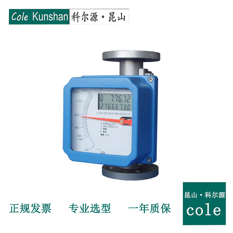
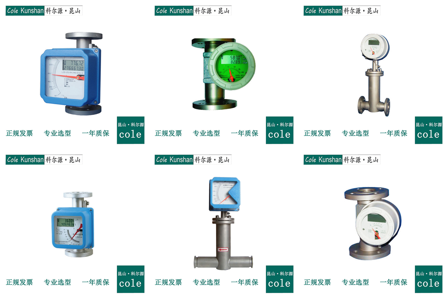
LZ series metal tube rotameter is a product with high technical content. Especially in the case of small pipeline flow, it has a good application prospect. At present, metal tube rotameter is mainly used in the flow measurement and automatic control system of liquid, gas and steam in petrochemical, metallurgy, electric power, medicine, food processing and other industries< br />
& nbsp;& nbsp; The measuring principle of LZ series metal tube rotameter is that the cone-shaped float moves in the reference orifice plate of the measuring tube with the center guide. The annular area between the two has a corresponding relationship with the flow rate. The position of the float is transferred to the indicator by the magnetic steel, and the flow rate is displayed locally. It can also be equipped with magnetoelectric converter to realize electric remote transmission, and the display of indicator is completely corresponding to the float movement.
2、 Basic technical parameters
Instrument precision: common type & plusmn; 5%, high precision & plusmn; 1.5%
Measuring medium: liquid, gas or steam
Ambient temperature: - 25 ℃~ + 55 ℃
Medium temperature: - 80 ℃~ + 400 ℃
With horizontal installation and vertical installation rotameter
Instrument range ratio: 10:1
Power supply: 24 VDC, 3.6 lithium battery
Influence of power supply voltage: & le& plusmn; 0.1%F.S
Load effect: & le& plusmn; 0.1%
Maximum working pressure: 4.0Mpa for DN 15-dn 50 and 1.6Mpa for DN 80-dn 150
Pipe connection: flange type, thread type, quick joint
Shell: aluminum alloy
Protection grade: IP65
Electrical connection: M20 & times; 1.5 internal thread, M16 & times; 1.5 internal thread, 1 / 2mpt
Electric remote converter: 4-20mA output signal, HART protocol communication
Material of measuring tube: common type is 1Cr18Ni9Ti, anticorrosive type is PTFE
Explosion proof: exdiibt1-t6
Intrinsically safe explosion proof: explosion proof sign exiaiict1-t6
Intrinsic safety parameters of power supply: UI = 28V Li = 100mA pi = 0.7W CI = 0nf Li = 0mh
Intrinsic safety parameters of alarm terminal: UI = 28V Li = 50mA pi = 0.1W CI = 0nf Li = 0mh
Basic type, anticorrosion type, high temperature type and jacket type are available
3、 Reference flow
Nominal diameter DN (mm)
measuring range
Pressure loss (kPa)
Water (L / h)
Air (m3 / h)
water
air
Common type
Anticorrosive type
Common type
Anticorrosive type
fifteen
2.5-25
-
0.07-0.7
six point five
-
seven point one
4.0-40
2.5-25
0.11-1.1
six point five
five point five
seven point two
6.3-63
4-40
0.18-1.8
six point six
five point five
seven point three
10-100
6.3-63
0.28-2.8
six point six
five point six
seven point five
16-160
10-100
0.48-4.8
six point eight
five point six
eight
25-250
16-160
0.7-7.0
seven
five point eight
ten point eight
40-400
25-250
1.0-10.0
eight point six
six point one
ten
63-630
40-400
1.6-16.0
eleven point one
seven point three
fourteen
twenty-five
100-1000
63-630
3-30
seven
five point nine seven
seven point seven
160-1600
100-1000
4.5-45
eight
six
eight point eight
250-2500
160-1600
7-70
ten point eight
six point eight
twelve
400-4000
250-2500
11-110
fifteen point eight
nine point two
nineteen
forty
500-5000
-
12-120
eight point eight
seven point six
seven point eight
600-6000
400-4000
16-160
eleven point six
nine point four
fourteen point five
fifty
630-6300
400-4000
18-180
eight point one
six point eight
eight point six
1000-10000
630-6300
25-250
eleven
nine point four
ten point four
1600-16000
1000-10000
40-400
seventeen
fourteen point five
fifteen point four
eighty
2500-25000
1600-16000
60-600
eight point one
six point nine
twelve point nine
4000-40000
2500-25000
80-800
nine point five
eight
eighteen point five
one hundred
6300-63000
4000-40000
100-1000
fifteen
eight point five
nineteen point two
one hundred and fifty
20000-100000
-
600-3000
nineteen point two
-
twenty.3
4、 Model description
Model specification table
LZ—
Metal tube rotameter
Code
indicator
Z
Basic indicator
D
Remote indicator
Code
Nominal diameter
-15
DN15
-25
DN25
-40
DN40
-50
DN50
-80
DN80
-100
DN100
-150
DN150
Code
structural style
/
Bottom in top out
H1
Left in right out
H2
Right in left out
AA
Side in side out
LA
Bottom in side out
S
Threaded connection
M
Quick coupling connection
Code
Body material
R1
321 stainless steel
R4
304 stainless steel
R6
316 stainless steel
R6L
316L stainless steel
Hc4
Ha C alloy
Ti
titanium
F
Lining F46 (PTFE)
Code
Indicator type
M7
Linear indicator
M9
Non linear indicator (local pointer shows instantaneous flow)
Code
Combination function
ESK
24VDC; Remote transmission of 4-20mA standard current signal
ESK-Z
24VDC; Remote transmission 4-20mA; On site LCD displays instantaneous and cumulative flow
ESK-D
On site lithium battery power supply; LCD displays instantaneous and cumulative flow
K1
With one on-line alarm point signal
K2
Bring down and on line alarm point signal
K12
With one online and one offline alarm point signal
Code
Explosion proof type
Ex
Intrinsically safe explosion proof
Exd
Flameproof
Code
Classification of measurement media
L
liquid
G
Gas
Code
Add function
T
The measuring tube is equipped with thermal insulation jacket
HT
The measured medium temperature is higher than 120 DEG; high temperature
5、 Converter form
6、 Outline and installation dimensions
The standard of jacket connecting flange is GB / t9119 pn1.6 DN 15
7、 Installation form
The flowmeter shall be installed vertically, and the angle between the center line and the plumb line of the flowmeter shall not exceed 5 deg;, In the upstream of the flowmeter, the inlet straight pipe section with five times of the nominal diameter shall be ensured, and in the downstream, the outlet straight pipe section with 250mm shall be ensured. If the medium contains solid impurities, a filter should be installed upstream of the flowmeter; If the medium contains ferromagnetic material, a magnetic filter should be installed upstream of the flowmeter. In order to facilitate maintenance and cleaning without affecting production, it is recommended to install bypass pipeline. In order to avoid the deformation of the flowmeter caused by the pipeline, the installation flange must be coaxial and parallel with the instrument, and the pipeline should be properly supported to avoid pipeline vibration and reduce the axial load of the flowmeter. The control valve in the measurement system should be installed downstream of the flowmeter. When it is used to measure gas, the pipeline pressure shall not be less than 5 times of the pressure loss of the flowmeter, so as to make the float work stably.
8、 Annex
Can provide users with front and rear straight pipe section, matching flange, magnetic filter, gas damping device and other accessories. If the medium contains ferromagnetic particles, a magnetic filter should be installed at the inlet of the flowmeter. The magnetic filter is equipped with magnetic rods arranged in a spiral way to minimize pressure loss. Each magnetic rod is wrapped by PTFE to prevent medium corrosion< br />
& nbsp; The structure of the magnetic filter is shown in Fig
9、 Limit switch alarm device
The part of the limit switch alarm device in the indicator is composed of induction head and aluminum sheet. The induction head is installed at the position where the aluminum sheet on the pointer shaft can be cut. The limit value can be set arbitrarily by changing the position of the induction head. The sensor outputs signal to the metal rotor flow indicating controller& nbsp;< br />
& nbsp; Technical parameters & nbsp< br />
& nbsp; 1. Power supply: 24 V AC & plusmn; 10%
& nbsp; 2. Power consumption: & le; 3W
& nbsp; 3. Working temperature: - 25 ℃ ~ 60 ℃ & nbsp< br />
& nbsp; 4. Output contact capacity: 24 VAC 3A < br / >
& nbsp; & nbsp; Wiring diagram
To change the alarm point, open the front cover, loosen the screw of the small pointer on the dial, adjust it to the required position, and then tighten the screwFinally, install the front cover.
10、 Design selection and ordering instructions
1. According to the measurement, the fluid is gas or liquidCorrect remote use of gas or liquid metal tube rotameter& nbsp;< br />
& nbsp; 2. The tested fluid is non corrosive and corrosion resistant& nbsp;< br />
& nbsp; 3. Please indicate the name of measured medium, flow rate, pipe diameter, working pressure, temperature, density and viscosity when ordering. Our company according to the user's density calibration correction, production of special flow scale& nbsp;< br />
& nbsp; 4. According to the measurement range and application of the fluid to be measured, select the appropriate type of specifications. If you have special requirements, please contact the company or the sales department.